- 您现在的位置:买卖IC网 > Sheet目录450 > ISL29120IROZ-T7 (Intersil)IC SENSOR LIGHT-DGTL I2C 6-ODFN
�� �
�
�ISL29120�
�Principles� of� Operation�
�Photodiodes� and� ADC�
�The� ISL29120� contains� three� photodiode� arrays,� which� convert�
�light� into� current.� The� spectral� response� for� red,� green� and� blue�
�color� ambient� intensity� sensing� is� as� shown� in� Figure� 2.� After�
�light� is� converted� to� current� during� the� light� to� signal� process,� the�
�current� output� is� converted� to� a� digital� count� by� an� on-chip�
�Analog-to-Digital� Converter� (ADC).� The� ADC� converter� resolution�
�is� selectable� from� 4,� 8,� 12� or� 16� bits.� The� ADC� conversion� time� is�
�inversely� proportional� to� the� ADC� resolution.�
�The� ADC� converter� uses� an� integrating� architecture.� This�
�conversion� method� is� ideal� for� converting� small� signals� in� the�
�presence� of� a� periodic� noise.� A� 100ms� integration� time� (16-bit�
�mode)� for� instance,� rejects� 50Hz� and� 60Hz� power� line� as� well� as�
�florescent� flicker� noise.�
�The� ADC� integration� time� is� determined� by� an� internal� oscillator�
�and� the� n-bit� (n� =� 4,� 8,� 12,� 16)� counter� inside� the� ADC.� A� good�
�balancing� act� of� integration� time� and� resolution� depends� on� the�
�application� for� optimum� system� performance.�
�The� ADC� provides� two� programmable� ranges� to� dynamically�
�accommodate� different� lighting� conditions.� For� dim� conditions,�
�the� ADC� can� be� configured� at� its� high� sensitivity� (low� optical)�
�range.� For� bright� conditions,� the� ADC� can� be� configured� at� its� low�
�sensitivity� (higher� optical)� range.�
�Note� that� the� effective� optical� sensitivity� of� the� ISL29120� in�
�terms� of� counts/� μW/cm� 2� is� directly� proportional� to� the� ADC�
�integration� time.�
�I� 2� C� Interface�
�There� are� eight� 8-bit� registers� inside� the� ISL29120� for�
�configuration,� control� and� status� indication.� The� two� command�
�registers� at� address� 0x00� and� 0x01� define� the� operation� of� the�
�device� and� provide� status� of� the� interrupt� events.� Two� 8-bit� read�
�only� registers� at� address� 0x02� and� 0x03� are� for� the� ADC� output.�
�These� registers� contain� the� results� of� the� latest� A/D� conversion.�
�Registers� 0x04� and� 0x05� contain� the� ‘low� threshold’� value� and�
�registers� 0x06� and� 0x07� store� the� ‘high� threshold’� value� for�
�interrupt� generation.�
�The� ISL29120’s� I� 2� C� interface� slave� address� is� internally� hard-wired�
�as� 1000110x,� where� x� is� R� (read)� or� W� (write)� bit.�
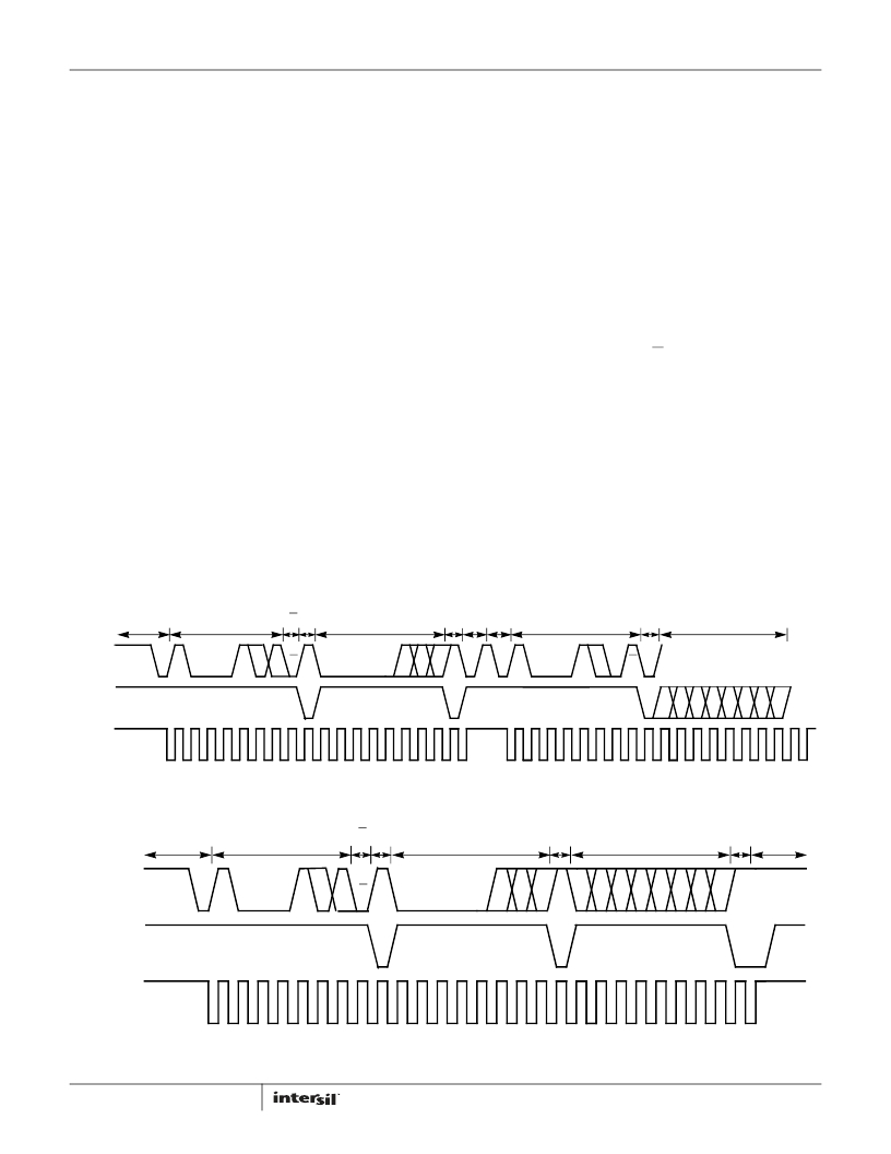
�Figure� 4� shows� a� sample� one-byte� read.� Figure� 5� shows� a� sample�
�one-byte� write.� The� I� 2� C� bus� master� always� drives� the� SCL� (clock)�
�line,� while� either� the� master� or� the� slave� can� drive� the� SDA� (data)�
�line.� Figure� 5� shows� a� sample� write.� Every� I� 2� C� transaction� begins�
�with� the� master� asserting� a� start� condition� (SDA� falling� while� SCL�
�remains� high).� The� following� byte� is� driven� by� the� master,� and�
�includes� the� slave� address� and� read/write� bit.� The� receiving� device�
�is� responsible� for� pulling� SDA� low� during� the� acknowledgement�
�period.� Every� I� 2� C� transaction� ends� with� the� master� asserting� a� stop�
�condition� (SDA� rising� while� SCL� remains� high).�
�For� more� information� about� the� I� 2� C� standard,� consult� the�
�Philips?� I� 2� C� specification� documents.�
�I� 2� C� DATA�
�START�
�DEVICE� ADDRESS�
�W� A�
�REGISTER� ADDRESS�
�STOP� START�
�DEVICE� ADDRESS�
�A�
�DATA� BYTE0�
�I� 2� C� SDA�
�IN�
�A6� A5� A4� A3� A2� A1� A0� W� A� R7� R6� R5� R4� R3� R2� R1� R0� A�
�A6� A5� A4� A3� A2� A1� A0� W�
�A�
�SDA� DRIVEN� BY� ISL29120�
�I� 2� C� SDA�
�OUT�
�SDA� DRIVEN� BY� MASTER�
�A�
�SDA� DRIVEN� BY� MASTER�
�A�
�SDA� DRIVEN� BY� MASTER�
�A� D7� D6� D5� D4� D3� D2� D1� D0�
�I� 2� C� CLK�
�1�
�2�
�3�
�4�
�5�
�6�
�7�
�8�
�9�
�1�
�2�
�3�
�4�
�5�
�6�
�7�
�8�
�9�
�1�
�2�
�3�
�4�
�5�
�6�
�7�
�8�
�9�
�1�
�2�
�3�
�4�
�5�
�6�
�7�
�8�
�9�
�FIGURE� 4.� I� 2� C� READ� TIMING� DIAGRAM� SAMPLE�
�I� 2� C� DATA�
�START�
�DEVICE� ADDRESS�
�W�
�A�
�REGISTER� ADDRESS�
�A�
�FUNCTIONS�
�A�
�STOP�
�I� 2� C� SDA� IN�
�A6� A5� A4� A3� A2� A1� A0�
�W�
�A�
�R7� R6� R5� R4� R3� R2� R1� R0�
�A�
�B7� B6� B5� B4� B3� B2� B1� B0�
�A�
�I� 2� C� SDA� OUT�
�SDA� DRIVEN� BY� MASTER�
�A�
�SDA� DRIVEN� BY� MASTER�
�A�
�SDA� DRIVEN� BY� MASTER�
�A�
�I� 2� C� CLK� IN�
�1�
�2�
�3�
�4�
�5�
�6�
�7�
�8�
�9�
�1�
�2�
�3�
�4�
�5�
�6�
�7�
�8�
�9�
�1�
�2�
�3�
�4�
�5�
�6�
�7�
�8�
�9�
�FIGURE� 5.� I� 2� C� WRITE� TIMING� DIAGRAM� SAMPLE�
�4�
�FN8314.0�
�May� 29,� 2012�
�发布紧急采购,3分钟左右您将得到回复。
相关PDF资料
ISL5216EVAL1
EVALUATION BOARD FOR ISL5216KI
ISL5217EVAL1
EVALUATION BOARD FOR ISL5217KI
ISL5239EVAL1
EVALUATION BOARD FOR ISL5239
ISL5239KIZ
IC LINEARIZER PRE-DISTORT 196BGA
ISL5416EVAL1
EVALUATION PLATFORM FOR ISL5416
ISL55005IEZ-T7
IC AMP MMIC BIPO BROADBND SC70-6
ISL55007IEZ-T7
IC AMP MMIC BIPO BROADBND SC70-6
ISL55008IEZ-T7
IC AMP MMIC BIPO BROADBND SC70-6
相关代理商/技术参数
ISL29125IROZ-T7
制造商:Intersil Corporation 功能描述:ISL29125IROZ PB-FREE RGB SENSOR WITH LITEFILM IR CUT & ORGAN - Tape and Reel
ISL29147IROMZ-T7
制造商:Intersil Corporation 功能描述:ISL29147IROMZ LOW POWER AMBIENT LIGHT & PROXIMITY SENSOR W/E - Tape and Reel 制造商:Intersil Corporation 功能描述:IC OPT SENSOR LIGHT-VOLT 8-ODFN 制造商:Intersil Corporation 功能描述:AMBIENT LIGHT & PROXIMITY SENSOR, ODFN-8, IC Function:Light to Digital Output Se
ISL2D-B
制造商:Rayovac 功能描述:TOOLS, FLASHLIGHTS (TORCHES), Body Material:Rubber, No. of Batteries:2 , RoHS Compliant: NA
ISL2D-BC
制造商:Rayovac 功能描述:2D INDL SWIVEL/BTRY
ISL3034E
制造商:INTERSIL 制造商全称:Intersil Corporation 功能描述:4-Channel And 6-Channel High Speed, Auto-direction Sensing Logic Level Translators
ISL3034E_09
制造商:INTERSIL 制造商全称:Intersil Corporation 功能描述:Best-in-Class ESD Protected Level Translators
ISL3034EIRTZ
功能描述:IC LEVEL TRANSLATOR 6CH 16-TQFN RoHS:是 类别:集成电路 (IC) >> 逻辑 - 变换器 系列:- 产品培训模块:Lead (SnPb) Finish for COTS
Obsolescence Mitigation Program 标准包装:100 系列:- 逻辑功能:变换器,双向 位数:2 输入类型:CMOS 输出类型:CMOS 数据速率:16Mbps 通道数:2 输出/通道数目:1 差分 - 输入:输出:无/无 传输延迟(最大):15ns 电源电压:1.65 V ~ 5.5 V 工作温度:-40°C ~ 85°C 封装/外壳:10-UFQFN 供应商设备封装:10-UTQFN(1.4x1.8) 包装:管件
ISL3034EIRTZ-T
功能描述:IC LEVEL TRANSLATOR 6CH 16-WQFN RoHS:是 类别:集成电路 (IC) >> 逻辑 - 变换器 系列:- 标准包装:1 系列:100ELT 逻辑功能:变换器 位数:1 输入类型:TTL 输出类型:差分 数据速率:- 通道数:2 输出/通道数目:1 差分 - 输入:输出:无/是 传输延迟(最大):0.6ns 电源电压:3 V ~ 3.8 V 工作温度:-40°C ~ 85°C 封装/外壳:8-SOIC(0.154",3.90mm 宽) 供应商设备封装:8-SOIC 包装:Digi-Reel® 产品目录页面:1088 (CN2011-ZH PDF) 其它名称:576-1360-6